[eHCI 스펙] 3. Data Structures
2022. 2. 22. 14:31해석
3. 데이터 구조
이 섹션은 interface 데이터 구조들을 정의합니다. 그 interface는 HCD (소프트웨어) 그리고 Enhanced Host Controller (하드웨어) 사이에 control, status 그리고 데이터 통신에 사용됩니다. 이 이 챕터에서의 데이터 구조 정의는 32-bit 메모리 버퍼 주소 공간을 지원합니다.
이 인터터페이스는 아래의 것들로 이루어져 있습니다.
- Periodic Schedule (주기적인 스케줄)
- Periodic Frame List (주기적인 프레임 리스트)
- Asynchronous Schedule (비동기 스케줄)
- Isochronous Transaction Descriptors (등시성 트랜잭션 디스크립터)
- Split-transaction Isochronous Transfer Decipptors (분할된 트랜잭션 등시성 전송 디스크릅터들)
- 큐 헤더, 큐 요소 전송 디스크립터
주기적인 프레임 리스트(periodic frame list)는, Host controller Interface를 위해, 모든 주기적인 통신 (등시성 전송 그리고 인터럽트 전송 타입) 지원의 핵심입니다.
이 비동기적인 리스트(asynchronous list)는 모든 bulk 그리고 control 전송 타입 지원의 핵심입니다.
- 등시성 전송 스트림은 Isochronous Transaction Descirptors (iTD)에 의해 관리되고,
- 등시성 분할-트랜잭션 데이터 스트림은 (Split-transaction Isochronous Transfer Descriptors) siTD로 관리됩니다.
모든 Interrupt, Control 그리고 Bulk 데이터 스트림은 queue heads와 Queue Element Transfer Descriptors (qTD)에 의해 관리됩니다.
원문
3. Data Structures
This section defines the interface data structures used to communicate control, status and data between HCD (software) and the Enhanced Host Controller (hardware). The data structure definitions in this chapter support a 32-bit memory buffer address space. Appendix B illustrates 64-bit versions of the interface data structures. The interface consists of a Periodic Schedule, Periodic Frame List, Asynchronous Schedule, Isochronous Transaction Descriptors, Split-transaction Isochronous Transfer Descriptors, Queue Heads and Queue Element Transfer Descriptors.
The periodic frame list is the root of all periodic (isochronous and interrupt transfer type) support for the host controller interface. The asynchronous list is the root for all the bulk and control transfer type support. Isochronous data streams are managed using Isochronous Transaction Descriptors (iTDs are described in Section 3.3). Isochronous split-transaction data streams are managed with Split-transaction Isochronous Transfer Descriptors (siTDs are described in Section 3.4). All Interrupt, Control and Bulk data streams are managed via queue heads (Section 3.6) and Queue Element Transfer Descriptors (qTDs described in Section
해석
이 데이터 구조들은 스케줄의 총 메모리 사용량(footporint)를 줄이기에 최적화 되어있습니다, 그리고 USB 트랜잭션을 수행하기에 필요한, (평균적으로) 메모리 엑세스 횟수도 줄이는데도 최적화되어있습니다.
소프트웨어는 EHCI host controller에 의해 도달할 수 있는, 인터페이스 데이터 구조(Interface data structre)가 4K 페이지 경계까지 걸치도록 보장해야합니다.
이 챕터에 정의된, 데이터 구조들은 (host controller의 관점에서) read only 그리고 read/write 가능한 필드들과 혼합되어있습니다. 이 host controller는 모든 data structrue 쓰는 것에, read-only 필드가 보존되어져야만 합니다.
원문
3.5).1 These data structures are optimized to reduce the total memory footprint of the schedule and to reduce (on average) the number of memory accesses needed to execute a USB transaction.
Note that software must ensure that no interface data structure reachable by the EHCI host controller spans a 4K page boundary.
The data structures defined in this chapter are (from the host controller’s perspective) a mix of read-only and read/writeable fields. The host controller must preserve the read-only fields on all data structure writes
원문
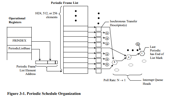
3.1 Periodic Frame List
This schedule is for all periodic transfers (isochronous and interrupt). The periodic schedule is referenced from the operational registers space using the PERIODICLISTBASE address register and the FRINDEX register. The periodic schedule is based on an array of pointers called the Periodic Frame List. The PERIODICLISTBASE address register is combined with the FRINDEX register to produce a memory pointer into the frame list. The Periodic Frame List implements a sliding window of work over time.
해석
3.1 주기적인 프레임 리스트
이 스케줄은 모든 주기적인 전송 (isochronous and interrupt, 등시성 및 인터럽트)를 위한 것 입니다.
이 주기적 스케줄은 PERIODICLISTBASE 주소 레지스터 그리고, FRINDEX 레지스터를 사용하는, 부가적인 레지스터의 공간으로부터, 레퍼런스 됩니다.
이 주기적인 스케줄은 Periodic Frame List로 불리우는 포인터들의 배열 기반으로 되어있습니다. 이 PERIODICLISTBASE 주소 레지스터는 메모리 포인터를 그 frame list로 생산하기 위해서, FRINDEX 레지스터와 혼합됩니다.
이 Periodic Frame List는 시간에 따른 작업의 슬라이딩 윈도우로 구현됩니다.
'영어 > 기술문서로 영어 공부하기' 카테고리의 다른 글
| USB eHCI에서 QH와 qTD의 의미 (0) | 2022.02.22 |
|---|---|
| [USB 스펙 2.0] 9.2.5 Power Management (0) | 2022.02.22 |
| [USB 2.0 스펙] Transfer Management (0) | 2022.02.15 |
| [USB 2.0 스펙] 9 USB Device Framework (0) | 2022.02.15 |
| [USB 2.0 스펙] 10.4 Host Controller Driver (0) | 2022.02.15 |